Ceramic Capacitor
What are ceramic capacitors?
 A ceramic capacitor uses a ceramic material as the dielectric. Ceramics were one of the first materials to be used in the production of capacitors, as it was a known insulator. Many geometries were used in ceramic capacitors, of which some, like ceramic tubular capacitors and barrier layer capacitors are obsolete today due to their size, parasitic effects or electrical characteristics. The types of ceramic capacitors most often used in modern electronics are the multi-layer ceramic capacitor, otherwise named ceramic multi-layer chip capacitor (MLCC) and the ceramic disc capacitor. MLCCs are the most produced capacitors with a quantity of approximately 1000 billion devices per year. They are made in SMD (surface-mounted) technology and are widely used due to their small size. Ceramic capacitors are usually made with very small capacitance values, typically between 1nF and 1µF, although values up to 100µF are possible. Ceramic capacitors are also very small in size and have a low maximum rated voltage. They are not polarized, which means that they may be safely connected to an AC source. Ceramic capacitors have a great frequency response due to low parasitic effects such as resistance or inductance.
Ceramic capacitor definition
A ceramic capacitor is a capacitor which uses a ceramic material as the dielectric. The two most common types are multi-layer ceramic capacitors and ceramic disc capacitors.
Characteristics
Precision and tolerances
There are two classes of ceramic capacitors available today: class 1 and class 2. Class 1 ceramic capacitors are used where high stability and low losses are required. They are very accurate and the capacitance value is stable in regard to applied voltage, temperature and frequency. The NP0 series of capacitors has a capacitance thermal stability of ±0.54% within the total temperature range of -55 to +125 °C. Tolerances of the nominal capacitance value can be as low as 1%.
Class 2 capacitors have a high capacitance per volume and are used for less sensitive applications. Their thermal stability is typically ±15% in the operating temperature range, and the nominal value tolerances are around 20%.
Size advantages
When high component packing densities are required, as is the case in most modern printed circuit boards (PCBs), MLCC devices offer a great advantage compared to other capacitors. To illustrate this point, the “0402” multi-layer ceramic capacitor package measures just 0.4 mm x 0.2 mm. In such a package, there are 500 or more ceramic and metal layers. The minimum ceramic thickness as of 2010 is on the order of 0.5 microns.
High voltage and high power
Physically larger ceramic capacitors can be made to withstand much higher voltages and these are called power ceramic capacitors. These are physically much larger than those used on PCBs and have specialized terminals for safe connection to a high voltage supply. Power ceramic capacitors can be made to withstand voltages in the range of 2kV up to 100 kV, with a power specified at much higher than 200 volt-amperes.
Smaller MLCCs used in printed circuit boards are rated to voltages from only a few volts up to several hundreds of volts, depending on the application.
Construction and properties of ceramic capacitors
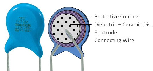
Ceramic disc capacitors
Ceramic disc capacitors are manufactured by coating a ceramic disc with silver contacts on both sides. To achieve larger capacitances, these devices can be made from multiple layers. Ceramic disc capacitors are usually through-hole components and are falling out of favor due to their size. MLCCs are used instead, if capacitance values allow. Ceramic disc capacitors have a capacitance value of 10pF to 100μF with a wide variety of voltage ratings, between 16 volts to 15 kV and more.
Multi-layer ceramic capacitor (MLCC)
MLCCs are manufactured by accurately mixing finely ground granules of paraelectric and ferroelectric materials and alternatively layering the mix with metal contacts. After the layering is complete, the device is brought to a high temperature and the mixture is sintered, resulting in a ceramic material of desired properties. The resulting capacitor basically consists of many smaller capacitors connected in parallel, increasing the capacitance. MLCCs consist of 500 layers and more, with the minimum layer thicknes of approximately 0.5 micron. As technology progresses, the layer thickness decreases and higher capacitances are achievable for the same volume.
MLCC case sizes
Surface-mount components like MLCCs are cheaper, because they have no leads and a little bit smaller than their counterparts with leads, and they need no holes in the PCB, a second reduction of costs. They are designed to be handled by machines rather than by humans, to reduce costs.
MLCCs are manufactured in standardized shapes and sizes for comparable handling. Because the early standardization was dominated by American EIA standards the dimensions of the MLCC chips were standardized by EIA in units of inches. A rectangular chip with the dimensions of 0.06 inch length and 0.03 inch width is coded as “0603”. This code is international and in common use.The EIA code and the metric equivalent of the common sizes of multilayer ceramic chip capacitors, and the dimensions in mm are shown in the following table. Missing from the table is the measure of the height "H". This is generally not listed, because the height of MLCC chips depends on the number of layers and thus on the capacitance. Normally, however, the height H does not exceed the width W.
| Drawing | EIA inch code | Dimensions L x W inch x inch | IEC/EN metric code | Dimensions L × W mm × mm | EIA inch code | Dimensions LxW inch x inch | IEC/EN metric code | Dimensions L × W mm × mm | |
|---|---|---|---|---|---|---|---|---|---|
 | 01005 | 0.016 × 0.0079 | 0402 | 0.4 × 0.2 | 1806 | 0.18 × 0.063 | 4516 | 4.5 × 1.6 | |
| 015015 | 0.016 x 0.016 | 0404 | 0.4 x 0.4 | 1808 | 0.18 x 0.079 | 4520 | 4.5 × 2.0 | ||
| 0201 | 0.024 × 0.012 | 0603 | 0.6 × 0.3 | 1812 | 0.18 × 0.13 | 4532 | 4.5 × 3.2 | ||
| 0202 | 0.02 x 0.02 | 0505 | 0.5 x 0.5 | 1825 | 0.18 x 0.25 | 4564 | 4.5 x 6.4 | ||
| 0302 | 0.03 x 0.02 | 0805 | 0.8 x 0.5 | 2010 | 0.20 × 0.098 | 5025 | 5.0 × 2.5 | ||
| 0303 | 0.3 x 0.03 | 0808 | 0.8 x 0.8 | 2020 | 0.20 x 0.20 | 5050 | 5.08 x 5.08 | ||
| 0504 | 0.05 x 0.04 | 1310 | 1.3 x 1.0 | 2220 | 0.225 x 0.197 | 5750 | 5.7 × 5.0 | ||
| 0402 | 0.039 × 0.020 | 1005 | 1.0 × 0.5 | 2225 | 0.225 x 0.25 | 5664/5764 | 5.7 x 6.4 | ||
| 0603 | 0.063 × 0.031 | 1608 | 1.6 × 0.8 | 2512 | 0.25 × 0.13 | 6432 | 6.4 × 3.2 | ||
| 0805 | 0.079 × 0.049 | 2012 | 2.0 × 1.25 | 2520 | 0.25 x 0.197 | 6450 | 6.4 x 5.0 | ||
| 1008 | 0.098 × 0.079 | 2520 | 2.5 × 2.0 | 2920 | 0.29 × 0.197 | 7450 | 7.4 × 5.0 | ||
| 1111 | 0.11 x 0.11 | 2828 | 2.8 x 2.8 | 3333 | 0.33 x 0.33 | 8484 | 8.38 x 8.38 | ||
| 1206 | 0.126 × 0.063 | 3216 | 3.2 × 1.6 | 3640 | 0.36 x 0.40 | 9210 | 9.2 x 10.16 | ||
| 1210 | 0.126 × 0.10 | 3225 | 3.2 × 2.5 | 4040 | 0.4 x 0.4 | 100100 | 10.2 x 10.2 | ||
| 1410 | 0.14 x 0.10 | 3625 | 3.6 x 2.5 | 5550 | 0.55 x 0.5 | 140127 | 14.0 x 12.7 | ||
| 1515 | 0.15 x 0.15 | 3838 | 3.81 x 3.81 | 8060 | 0.8 x 0.6 | 203153 | 20.3 x 15.3 |
MLCC capacitance ranges
The picture right shows the maximum capacitance for class 1 and class 2 multilayer ceramic chip capacitors. The following three tables, for ceramics NP0/C0G and X7R each, list for each common case size the maximum available capacitance value and rated voltage of the leading manufacturers Murata, TDK, KEMET, AVX. (Status 2013)Capacitance of MLCC chips depends on the dielectric, the size and the required voltage (rated voltage). Capacitance values start at about 1pF. The maximum capacitance value is determined by the production technique. For X7R that is 47 µF, for Y5V: 100 µF.
Maximum capacitance values of class 1 NP0/C0G MLCC chips
Rated-
voltage Case size, EIA Code
Dimensions in mm 0201 0402 0603 0805 1206 1210 1812 0.5×0.3 1.0×0.5 1.6×0.8 2.0×1.2 3.2×1.6 3.2×2.5 4.5×3.2 Max. capacitance 25 V 100 pF 2.2 nF 15 nF 47 nF 100 nF 220 nF - 50 V 220 pF 1.5 nF 6.8 nF 33 nF 100 nF 150 nF 220 nF 100 V – 1 nF 4.7 nF 15 nF 47 nF 100 nF 150 nF 250 V – – 680 pF 2.2 nF 6.8 nF 15 nF 47 nF 630 V – – – – 3.3 nF 6.8 nF 22 nF 1000 V – – – 120 pf – 680 pF 2.2 nF
Maximum capacitance values of class 2-X7R-MLCC chips
Rated-
voltage Case size, EIA Code
Dimensions in mm 01005 0201 0402 0603 0805 1206 1210 1812 2220 0.25×0.12 0.5×0.3 1.0×0.5 1.6×0.8 2.0×1.2 3.2×1.6 3.2×2.5 4.5×3.2 5.7×5.0 Max. capacitance 6.3 V – – 1.0 µF 2.2 µF 10 µF – 47 µF – - 10 V 1.5 nF 10 nF 680 nF 2.2 µF 10 µF 22 µF 47 µF - 16 V – 4.7 nF 220 nF 470 nF 4.7 µF 10 µF 22 µF 33 µF 47 µF 25 V 1.5 nF 3.3 nF 100 nF 470 nF 2.2 µF 4.7 µF 10 µF 22 µF 10 µF 50 V - 1.5 nF 100 nF 1.0 µF 4.7 nF 10 µF 22 µF 22 µF 22 µF 100 V – – 4.7 nF 100 nF 0.47 µF 2.2 µF 2.2 µF 2.2 µF 4.7 µF 250 V – – – 2.2 nF 22 nF 100 nF 220 nF 0.47 µF 1.0 µF 630 V – – – – – 33 nF 68 nF 0.1 µF 0.22 µF 1000 V – – – – – 4.7 nF 22 nF 47 nF 100 nF 2000 V – – – – – – – 4.7 nF 10 nF
voltage
Dimensions in mm
voltage
Dimensions in mm
RFI/EMI suppression ceramic capacitors

Typical ceramic disc capacitor for EMI/RFI suppression for safety standard classes X1/Y2

Ceramic feedthrough capacitor for noise filtering

Multilayer ceramic capacitor (MLCC)
Mainly because of their nonflammability in case of short circuit and their compatibleness against high peak overvoltages (transient voltage), ceramic capacitors are often used as AC line filters for electromagnetic Interference (EMI) or radio Frequency Interference (RFI) suppression. These capacitors, also known as safety capacitors, are crucial components to reduce or suppress electrical noise caused by the operation of electrical or electronic equipment, while also providing limited protection against human endanger during short circuitsSuppression capacitors are effective interference reduction components because their electrical impedance decreases with increasing frequency, so that at higher frequencies they short circuit electrical noise and transients between the lines, or to ground. They therefore prevent equipment and machinery (including motors, inverters, and electronic ballasts, as well as solid-state relay snubbers and spark quenchers) from sending and receiving electromagnetic and radio frequency interference as well as transients in across-the-line (X capacitors) and line-to-ground (Y capacitors) connections. X capacitors effectively absorb symmetrical, balanced, or differential interference. Y capacitors are connected in a line bypass between a line phase and a point of zero potential, to absorb asymmetrical, unbalanced, or common-mode interference.
RFI/EMI suppression with X- and Y-capacitors for equipment without and with additional safety insulation
EMI/RFI suppression capacitors are designed so that any remaining interference or electrical noise does not exceed the limits of EMC directive EN 50081.Suppression components are connected directly to mains voltage for 10 to 20 years or more and are therefore exposed to potentially damaging overvoltages and transients. For this reason, suppression capacitors must comply with the safety and inflammability requirements of international safety standards such as
Europe: EN 60384-14,
USA: UL 1414, UL 1283
Canada: CSA C22.2, No.1, CSA C22.2, No.8
China: CQC (GB/T 14472-1998)
RFI capacitors that fulfill all specified requirements are imprinted with the certification mark of various national safety standards agencies. For power line applications, special requirements are placed on the inflammability of the coating and the epoxy resin impregnating or coating the capacitor body. To receive safety approvals, X and Y powerline-rated capacitors are destructively tested to the point of failure. Even when exposed to large overvoltage surges, these safety-rated capacitors must fail in a fail-safe manner that does not endanger personnel or property.
As of 2012 most ceramic capacitors used for EMI/RFI suppression were leaded ones for through-hole mounting on a PCB,he surface-mount technique is becoming more and more important. For this reason, in recent years a lot of MLCC chips for EMI/RFI suppression from different manufacturers have received approvals and fulfill all requirements given in the applicable standards.
Ceramic power capacitors
Different styles of ceramic capacitors for power electronic
Doorknob style high voltage ceramic capacitor

Disc Plate style RF power ceramic capacitor


Although the materials used for large power ceramic capacitors mostly are very similar to those used for smaller ones, ceramic capacitors with high to very high power or voltage ratings for applications in power systems, transmitters and electrical installations are often classified separately, for historical reasons. The standardization of ceramic capacitors for lower power is oriented toward electrical and mechanical parameters as components for use in electronic equipment. The standardization of power capacitors, contrary to that, is strongly focused on protecting personnel and equipment, given by the local regulating authority.Power ceramic capacitors in a radio-frequency transmitter station
As modern electronic equipment gained the ability to handle power levels that were previously the exclusive domain of "electrical power" components, the distinction between the "electronic" and "electrical" power ratings has become less distinct. In the past, the boundary between these two families was approximately at a reactive power of 200 volt-amps, but modern power electronics can handle increasing amounts of power.
Power ceramic capacitors are mostly specified for much higher than 200 volt-amps. The great plasticity of ceramic raw material and the high dielectric strength of ceramics deliver solutions for many applications and are the reasons for the enormous diversity of styles within the family of power ceramic capacitors. These power capacitors have been on the market for decades. They are produced according to the requirements as class 1 power ceramic capacitors with high stability and low losses or class 2 power ceramic capacitors with high volumetric efficiency.
Class 1 power ceramic capacitors are used for resonant circuit application in transmitter stations. Class 2 power ceramic capacitors are used for circuit breakers, for power distribution lines, for high voltage power supplies in laser-applications, for induction furnaces and in voltage-doubling circuits. Power ceramic capacitors can be supplied with high rated voltages in the range of 2 kV up to 100 kV
The dimensions of these power ceramic capacitors can be very large. At high power applications the losses of these capacitors can generate a lot of heat. For this reason some special styles of power ceramic capacitors have pipes for water-cooling.
Applications for ceramic capacitors

Having in mind that MLCCs are the most widely produced capacitor in the electronics industry, it goes without saying that there are countless applications for these capacitors. An interesting high-precision, high-power application is a resonant circuit in transmitter stations. Class 2 high-power capacitors are used in high voltage laser power supplies, power circuit breakers, induction furnaces etc. Small-form SMD (surface mount) capacitors are often used in printed circuit boards and high density applications use capacitors which are comparable to the size of a grain of sand. They are also used in DC-DC converters which put a lot of stress on the components in the form of high frequencies and high levels of electrical noise. Ceramic capacitors can also be used as a general purpose capacitor, since they are not polarized and are available in a large variety of capacitances, voltage ratings and sizes. Many hobbyists, especially in the field of robotics, are familiar with ceramic disc capacitors used across brush DC motors to minimize RF noise
If you
need more information please contact our sales & Engineering at
sales@maxcapacitor.com.